
POX Controller and Click in practice
How to create a simple SDN and NFV application
This is the first project I did for learning Software Defined Networking and Network Function Virtualization. It makes use of Mininet for network virtualization, POX for the python SDN Controller application and Click Modular Router for networking functions like Load Balancing, IDS and NAPT.
- How to setup a topology with Mininet.
- How to program POX SDN controller and Switches with OpenFlow.
- How to integrate network functions with Click.
Here is the link to the Github repo containing the project.
Services
These services will run Click:
- lb1: will serve DNS requests and load balance them towards the three ds servers.
- lb2: will serve WEB requests and load balance them towards the three ws servers.
- ids: is an Intrusion Detection System which will do basic filtering on HTTP requests and direct the suspicious ones to the inspector machine, while others will go through to the lb2.
- napt: is the Network Address and Port Translator, will translate addresses from the private network 10.0.0.0/24 to 100.0.0.0/24.
These will run POX l2.learning modules:
- Fw1 and Fw2 are firewalls filtering traffic from/to the Demilitarized Zone and Private Zone.
- All the others sw are simple L2 Learning switches.
1. Mininet Topology
Mininet allows to virtualize a network adding hosts, switches and links as you prefer.
How to run mininet:
- In Mininet you just need a single python file.
- Define your Topology class extending Topo
- Start the mininet with your topology and a controller.
Before launching the mininet script, check ovs-ctl is running, otherwise:
$ sudo /usr/share/openvswitch/scripts/ovs-ctl start
This is a mininet example
#!/usr/bin/python2

from mininet.net import Mininet
from mininet.cli import CLI
from mininet.topo import Topo
from mininet.node import RemoteController, OVSSwitch, Host

class MyTopology(Topo):
    def __init__(self):
        Topo.__init__(self)
        # All the elements are basically L2 switches
        sw1 = self.addSwitch("sw1", dpid=int2dpid(1))
        .
        .
        # Add Hosts
        h1 = self.addHost("h1", ip="100.0.0.10/24")
        .
        .
        # Add Links
        self.addLink(h1, sw1)               #Create link
        .
        .
Importantly every mininet object has a DPID which we can set and can refer later.
Then in the main: (we use a local controller)
if __name__ == "__main__":
    topo = MyTopology()
    ctrl = RemoteController("c0", ip="127.0.0.1", port=6633)
    net = Mininet(  topo=topo,
                    switch=OVSSwitch,
                    controller=ctrl,
                    autoSetMacs=True,
                    autoStaticArp=True,
                    build=True,
                    cleanup=True)

    net.start()
    ##################
    # Launch services and tests here
    ...
    ###########
    CLI(net)
    net.stop()
We can launch services in mininet hosts like this:
net.get("ws1").cmd("python3 -m http.server 80 &")
CLI(net) allows to have an interactive shell on the mininet environment while it is running.
You can run commands easily.
mininet> h1 ping h2
After the inline command exit, net.stop() will gracefully stop the network.
If you want to clean the system from the last mininet run, execute:
$ sudo mn -c
2. POX Controller
The controller has the role of setting up rules in the OpenFlow switches whenever they encounter a packet for which no routing decision can be made.
The POX controller handles persistent connections from OpenFlow enabled switches, and has a handler for each state of the connection.
For example, each event will fire the appropriate callback:
- _handle_ConnectionUp
- _handle_ConnectionDown
- _handle_PacketIn
- _handle_PortStatus
- _handle_FlowRemoved
- _handle_ErrorIn
- _handle_BarrierIn
We will focus on the first three: when a SW will first connect, when it will disconnect, and whenever a packet is forwarded from the SW to the Controller.
In this case we use the already present l2 forwarding module which implements standard switch behavior with flood and learn mechanism. We extend that module for the two firewalls adding the rules to block/allow traffic based on port/destination address.
Main controller file
The main controller application can be like this:
#!/bin/python2
from pox.core import core
from forwarding.l2_learning import *

# importing MY modules
from myproj.myfw import MyFw2, MyFw1
from myproj.l2_custom import l2_learning_custom
from myproj.clickElem import click_device

def launch():
    fw_list_dpid = [51, 52]
    click_dpid = [71,72,73, 74]

    private_ip_hosts = ["10.0.0.50", "10.0.0.51"]
    srv_list = {"dns":["100.0.0.20", "100.0.0.21", "100.0.0.22"],
                "web":["100.0.0.40", "100.0.0.41", "100.0.0.42"]}

    # registering the two firewalls
    core.registerNew(MyFw1, fw_list_dpid[0] , srv_list)
    core.registerNew(MyFw2, fw_list_dpid[1], private_ip_hosts, srv_list)
    # registering click elements (napt, ids and lb)
    core.registerNew(click_device, click_dpid)

    # Except firewalls, click elements all the others are l2 learning switches
    core.registerNew(l2_learning_custom, click_dpid + fw_list_dpid)
With the DPID list we can set which registered module handle which element. In fact, click_device class will handle DPID 71,72,73,74.
The class l2_learning_custom takes as argument a list of DPID to ignore, so works in reverse as the others.
Registering a new element will allow each component to manage every incoming switch connection, so a way to distinguish which switch is connecting is to use each DPID as a filter.
Ex: If Fw1 has to manage the DPID 51, then when _handle_ConnectionUp is raised, we can continue only if the event.dpid is 51.
Custom component and OpenFlow rule install
Here we see the base MyFirewall class. It will install the rules to the switches as soon as they come up and connect to the controller.
from pox.core import core
from pox.lib.addresses import IPAddr
from forwarding.l2_learning import *
import pox.openflow.libopenflow_01 as of
import pox.lib.packet as PKT

class MyFirewall(object):
    def __init__(self, fw_dpid, srv_list):
        # we need to attach this class as listener
        core.openflow.addListeners(self)
        self.fwdpid = fw_dpid
        self.srv_list = srv_list
    #
    #   Common rules to both firewalls 1 & 2
    #
    def _handle_ConnectionUp(self, event):
        # just handle the switches with the wanted DPID
        if event.dpid == self.fwdpid:
            # save the connection object
            self.connection = event.connection
            log.debug("Firewall %d : %s has come up." ,
                            event.dpid, dpid_to_str(event.dpid))

            ########## INSTALL THE RULES ON THE SWITCH ##########
            rules = set()
            for web_server in self.srv_list["web"]:
                # generating TCP rules for communication to web servers
                # from out (public/private zone) to inner
                msg = of.ofp_flow_mod(
                    action = of.ofp_action_output(port=2),
                    match = of.ofp_match(
                            in_port = 1,
                            dl_type = PKT.ethernet.IP_TYPE,
                            nw_proto = PKT.ipv4.TCP_PROTOCOL,
                            nw_dst = IPAddr(web_server),    # src=internal IP
                            tp_dst = 80
                        ),
                    priority = 111
                )
                print("ALLOWING TCP 80 in FW {} to {}".format(
                                            event.dpid, web_server))
                rules.add(msg)

                # From inner web services to the outer (public/private zone)
                msg = of.ofp_flow_mod(
                    action = of.ofp_action_output(port=1),
                    match = of.ofp_match(
                            in_port = 2,
                            dl_type = PKT.ethernet.IP_TYPE,
                            nw_proto = PKT.ipv4.TCP_PROTOCOL,
                            nw_src = IPAddr(web_server),    # src=internal IP
                            tp_src = 80
                        ),
                    priority = 111,
                )
                rules.add(msg)
                print("ALLOWING TCP 80 in FW {} from {}".format(
                                            event.dpid, web_server))

                ...
                ...
            # send out all the collected generated rules to the switch
            for rule in rules:
                self.connection.send(rule)

            # then act as normal L2 Switch
            LearningSwitch(event.connection, False)
You have to install a rule for each direction of the flow, indeed two rules are needed.
NOTE: remember to set the right priorities for the right rule ordering.
Each rule has an:
- action: for example ofp_action_output will send pkt to the port
- match: will match pkt based on protocol, ports, and type
- priority: higher priority takes over
Then I expanded the MyFirewall class to add functionalities unique to each firewall fw1/fw2.
How to run POX Controller
You can start the controller with:
$ sudo python2 pox.py my_controller samples.pretty_log log.level --DEBUG
you add the modules you want to run, here we added pretty_log.
How to check active flows
Once you run a basic topology and a controller you can check at any time active flows with:
# view flows
$ sudo ovs-vsctl show
# view flow details
$ sudo ovs-ofctl dump-flows s1
3. Click programming
With Click we can program mininet Switches with our own Virtualized Network Functions, without the need of any controller. Here we see some basic examples.
What is Click (The Click Modular Router)
Click Modular Router is a fast C++ router implementation with its own driver for handling traffic which provide extremely efficient routing and packet processing. Click allows to build highly customizable router functions, with extreme ease of deployment and gives an extensible language to do it.
This way routers can be implemented in linux hardware in a more efficient way, in fact Click achieves a very high forwarding rate per second. To do so Click gets rid of the interrupt driven architecture in favor of polling, avoiding expensive context switch and memory accesses.
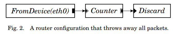
In Click there are Elements with input and output ports. For example FromDevice(eth0) gets all the packets from the eth0 interface.
In click you attach element with ->. Infact FromDevice(eth0)->Print is an example. For each element, you must link each input and output port, no spare ports are allowed.
See for example: (Image from Click white paper here)
Here there is the official wiki for Click
A Click Network Address Port Translator
Create a plain file, napt.click for example.
First we have to get the input and output port of the switch. (only shown from one side, the same is for the internal interface).
NOTE: you first have to get the interface names which are generated by Mininet.
// setup ifaces
from_ext  :: FromDevice($ext_if, METHOD LINUX, SNIFFER false);
to_ext  :: ToDevice($ext_if, METHOD LINUX);

to_ext_queue :: Queue(1024) -> to_ext;
In order to be able to send out on the same interface from multiple sources we need to set up a Queue object which can take multiple inputs, otherwise we are restricted to just one.
Then we differentiate the traffic, ARP requests, response and normal IP traffic with a Classifier which match on specific bits. (4th argument means “all the others”)
// ARPR, ARR , IP Classifiers, other traffic
from_ext -> ext_cl :: Classifier(12/0806 20/0001, 12/0806 20/0002, 12/0800, -);
Then the instantiated ext_cl Classifier will have 4 output ports which will need to be dealt with.
// respond to ARP queries for the router external interface

ext_cl[0] -> ARPResponder(DmZ) -> Print("ARP_R_ext") -> to_ext_queue ;
ext_cl[1] -> [1]arp :: ARPQuerier(DmZ);

//Discard non-IP, non-ARP packets
ext_cl[3] -> Print("DISCARDING NON IP PACKET") -> to_drop1 -> Discard;
- ext_cl[0]: here arrives an ARP query, so the
ARPResponderwill reply with the indicated values andPrintit, then the response will be sent back to the same interface. - ext_cl[1]: here arrives ARP responses, so the role of the
ARPQuerieris to save the value locally. - ext_cl[3]: discard every other NON IP packet.
Then we classify the IP traffic:
// Classifying IP traffic
ext_cl[2] ->  Strip(14) -> CheckIPHeader
    -> ext_ipc :: IPClassifier(
    // ping from out to gateway
        icmp && icmp type echo and dst $sw_ext_ip,
    // tcp udp traffic from ext to inside
        dst $sw_ext_ip and (tcp or udp),
    // ping response
        proto icmp && icmp type echo-reply,
    // others
        -
    );
From here we can deal singularly with TCP or UDP packets, ICMP packets or anything else.
For example we want to be able to respond to ICMP echo requests with:
// send back pings gw to outside
ext_ipc[0] -> Print("ICMP ECHO FROM EXT->GW")
    -> ICMPPingResponder
    -> to_ext_arp_queue ;
And here it finally comes the network translation part with an IPRewriter:
rw :: IPRewriter(pattern $sw_ext_ip 1024-65534 - - 0 1);

rw[0] -> to_ext_arp_queue;
rw[1] -> to_in_arp_queue;

// FROM INTERNAL

int_ipc[1] -> Print("IP from INT to EXT") -> [0]rw;

// FROM EXTERNAL

ext_ipc[1] -> Print("IP from EXT to INT") -> [0]rw;
Here the Rewriter takes as input the IP address to rewrite to and a range of ports, all fields are optional and you can decide. Lastly, 0 and 1 are the output device ports. In fact here we are translating packets IP address with the external facing router IP and sending them to the external interface which is 0.
src(10.0.0.90) –> napt –> src(100.0.0.1)
When the packets come back, the Rewriter keeps its mappings and will rewrite the same packet and send it to the internal network from the port 1.
You have to send the TCP and UDP packets ( ext_ipc[1] ) to the port 0 of the Rewriter.
And now you have your basic NAPT. Check the full examples on the github repo.
To run click (with example interfaces) :
$ sudo /usr/local/bin/click -f napt.click int_if=ids-eth3 ext_if=ids-eth1
You can pass arguments like that, and each argument will be saved in its own variable.
How to manage Click from POX SDN controller
We manage to run each .click file when the designated Mininet switch object will connect to the POX Controller. From there we can distinguish each one with its own DPID and launch the appropriate Click file.
In POX I registered a new component called clickElem which will handle the connecting devices we want to run click on. A list of click elements DPIDs will be given as input.
Within the _handle_ConnectionUp event handler:
if event.dpid not in self.clicks_dpids:
    log.debug("Ignoring connection from {}".format(event.dpid))
    return
log.debug("Connection from CLICK: [{}] - {} ".format(event.dpid, event.connection))
# start click modules
click_path = "../nfv"
# launch lb1 (DNS side)
if event.dpid == 71:
    args = "sudo /usr/local/bin/click -f " + click_path + "/lb.click int_if=lb1-eth2 ..."
# launch lb2 (HTTP side)
elif event.dpid == 72:
    args = "sudo /usr/local/bin/click -f " + click_path + "/lb.click int_if=lb2-eth2 ... "
# launch ids
elif event.dpid == 73:
    args = "sudo /usr/local/bin/click -f " + click_path + "/ids.click int_if=ids-eth3 ... "
# launch napt
elif event.dpid == 74:
    args = "sudo /usr/local/bin/click -f " + click_path + "/nat.click int_if=napt-eth2 ... "

# launch the process
log.debug("[{}] RUN: {}".format(event.dpid, args ))
args = shlex.split(args)
self.click_proc = subprocess.Popen(args)
Run
Start the Mininet Topology
$ make topo
Start the POX SDN Controller
$ make app
Close everything and clean
$ make clean