
How to configure Cisco routers with routing protocols.
BGP, OSPF, HSRP and Multicast routing. [PART 1]
Let’s set up a virtual router environment from scratch!
Last modified: 26 January 2022
Hello everybody, in this post we are going to learn step by step how to setup a fully functioning network environment with the help of Graphical Network Simulator-3 (GNS3). This exercise aims to be helpful with the study of network routing protocols.
We are going to create an ISP basic network.
- Network topology explanation.
- Routing protocol choices.
- Fault tolerant routing.
- Multicast routing.
The full code configuration of the four Cisco routers is found at the end of the page.
| Table of Acronyms | |
|---|---|
| BGP | Border Gateway Protocol |
| OSPF | Open Shortest Path First |
| RIP | Routing Information Protocol |
| AS | Autonomous System |
| HSRP | Hot Standby Router Protocol |
| PIM | Protocol Independent Multicast |
| RP | Rendezvous Point |
Network Equipment (virtual)
- 4 Cisco 7301 routers
- 2 HP2524 switches (one is for server network and one for client network)
- Virtual Machines (both on server and client network)
Network Topology
The network topology we are going to recreate is described as follow:
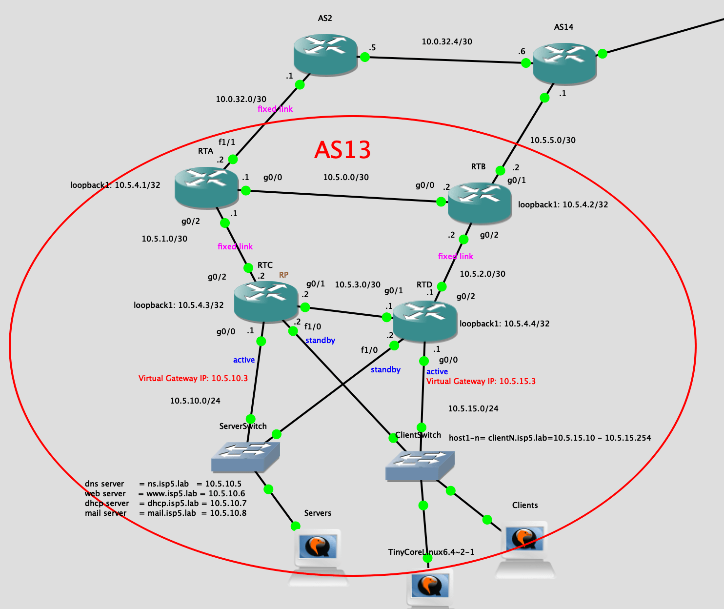
Let’s explain the topology in details.
- The AS13 is our competence Autonomous System and we can consider it as managed by our ISP called isp5.
- AS2 is considered the router connected to the backbone network, providing connectivity.
- AS14 is considered an other ISP’s border router.
- AS14 is also considered a Peering ISP, meaning in case of network failures, traffic can flow from one ISP to the other to allow Internet reachability.
Inside our AS13:
- RTA and RTB are area border routers. They are both e-BGP (to the outside) and i-BGP (to the inside) peers.
- RTA is e-BGP peering with AS2. RTB is e-BGP peering with AS14. Internally, RTA and RTB are i-BGP peers.
- RTC and RTD provide fault tolerant access to server and client networks respectively.
Dynamic IP routing
For the internal routing, Open Shortest Path First or OSPF version 2 will be used. RTA and RTB will also advertise the default route through OSPF.
Border Gateway Protocol or BGP is used for external routing AS13-AS2 and AS13-AS14:
- To direct the traffic we will set BGP local preferences for routes from AS2 and AS14.
- RTA and RTB will advertise AS13’s OSPF paths to AS2 and AS14.
- Routes coming from AS2 will have higher local preference value and will be the preferred ones.
The link RTA-AS2 is called primary link.
The link RTB-AS14 is called private link.
OSPF Configuration
Let’s assume each router has its interfaces already configured with the IP addresses shown in the Figure 1.
Firstly for each router we set up the router-id correspondent to the router loopback address with: (RTA’s OSPF mode example)
router-id 10.5.4.1
In RTA’s OSPF setting, we will use “default-information originate always metric 20” to distribute default route to RTC and RTD. This default route points to RTA. RTB will not apply this default route since it is also a border router.
In RTB’s OSPF setting, we will use “default-information originate always metric 200” to distribute default route to RTC and RTD. This default route points to RTB. RTA will not apply this default route since it is also a border router.
[Note] RTA’s metric 20 < RTB’s metric 200.
Why? Because we want to route traffic to the peering ISP only if some failures happen on the primary link.
Then RTC and RTD will choose RTA as default route destination but NOTE, in RTC and RTD’s routing table, the default route only shows the next-hop.
If the primary link is down, RTC and RTD will send the packets outside only through RTB. RTB will then forward the packets to the outside using the private link. If RTA is down, RTC and RTD will choose RTB as default route destination.
RTA OSPF Configuration
router ospf 1
    router-id 10.5.4.1
    network 10.5.1.0 0.0.0.3 area 0
    network 10.5.0.0 0.0.0.3 area 0
    network 10.5.4.1 0.0.0.0 area 0
    default-information originate always metric 20
    exit
[for newcomers]
network <ip-address> <wildcard-mask> area <area-id>: Defines an interface on which OSPF runs and defines the area ID for that interface.
For each router we are telling OSPF to advertise the ip and the netmask reachable by the router to the selected area (in this case 0, backbone).
After this step each router should be able to discover and communicate to each other.
For every possible information about OSPF commands and configuration the Cisco OSPF official guide is a must read.
Other routers OSPF configurations are at the end of the article.
BGP configuration
Firstly for each router we set up the router-id correspondent to the router loopback address with:
bgp router-id 10.5.4.1
In RTA’s BGP setting, we aggregate the addresses to 10.5.0.0/20 (since our network is using this segment we don’t want to advertise multiple useless routes, just the main one is necessary to reach AS13). We also redistribute our OSPF route in BGP (or we could add RTA’s nearby network 10.5.0.0/30 and 10.5.1.0/30). This is done with: (RTA)
aggregate-address 10.5.0.0 255.255.240.0 summary-only
In RTA’s routing table, we also add a static route to RTB’s Loopback address for network 10.5.5.0/30. Since we use aggregate-address in RTA’s BGP setting, it will include 10.5.5.0/30. Actually RTA does not know where RTB’s Loopback is at all. RTB will not advertise that network to OSPF or BGP. This is done with: (RTA)
ip route 10.5.5.0 255.255.255.252 10.5.4.2
In addition, we are also using Loopback of RTA and RTB to establish the BGP TCP connections. This avoids failed interfaces and links with the help of OSPF routing.
BGP neighbors
Next we set up the BGP peering with AS2 and AS14.
In RTA we will set up AS2 as E-BGP peer and RTB as I-BGP peer.
We set up the neighboring to the destination IP as:
neighbor 10.0.32.1 remote-as 2
neighbor 10.5.4.2 remote-as 13
Next we set up the next-hop-self bgp attribute.
neighbor 10.5.4.2 next-hop-self
When a new route from an e-bgp peer is learned from RTA, the internal peer (RTB) will learn the prefix through i-bgp. If RTB does not have a route towards that IP, RTB will not be able to forward packets. The next-hop-self BGP attribute allow the internal bgp peer (RTB) to set the RTA address as ‘next-hop’ for routes learned from i-bgp. This way RTB will forward packets to RTA, and than it is RTA responsibility to forward out those packets.
BGP gives us an option to change the source of packets sent. In this case we can use Loopback interface as source of BGP packets sent between these neighbors. This way if one of the paths fails, the other will be used. Moreover by using loopback interface as update source, the benefit is that the BGP session won’t go down when physical interface goes down.
neighbor 10.5.4.2 update-source loopback 1
Finally to redistribute OSPF routes into BGP:
redistribute ospf 1
Complete BGP configuration of Router RTA
router bgp 13
    bgp router-id 10.5.4.1
    aggregate-address 10.5.0.0 255.255.240.0 summary-only
    redistribute ospf 1
    neighbor 10.0.32.1 remote-as 2
    neighbor 10.0.32.1 route-map PREF_FROM_AS2 in
    neighbor 10.5.4.2 remote-as 13
    neighbor 10.5.4.2 next-hop-self
    neighbor 10.5.4.2 update-source loopback 1
    no auto-summary
    no synchronization
    exit
Fault-tolerant IP routing
From AS13 To the Internet
We are going to set up our AS13 area with one back up link.
- When the link RTA-AS2 is operating without errors, all the AS13’s traffic will be routed to the Internet through the link RTA-AS2 with the use of BGP.
- When the link RTA-AS2 is down, for whatever reason, all traffic will be routed to the backup link RTB-AS14. From there, the peering ISP will forward the traffic correctly to the AS2.
When the link to AS2 is down, after a timer timeout, RTB will spread its BGP route to OSPF so that the default route to AS2 will be through AS14.
How to setup primary and secondary link
To set default route to RTA, and back up route to RTB for outgoing connections to outside we first create a route-map for incoming routes in BGP config mode: (RTA)
neighbor 10.0.32.1 route-map PREF_FROM_AS2 in
exit
“PREF_FROM_AS2” is the name of the route-map. It means “all the routes coming (in) from AS2”.
then we define the route-map this way: (RTA)
route-map PREF_FROM_AS2 permit 20
set local-preference 300
exit
While in RTB the local preference is lower:
neighbor 10.5.5.1 route-map PREF_FROM_AS14 in
exit
route-map PREF_FROM_AS14 permit 10
set local-preference 200
exit
Multicast Routing
RTC’s loopback1 will act as PIM Rendezvous Point RP. In addition, we will not enable PIM on RTA and RTB’s fa1/1 interfaces avoiding multicast protocol to affect other AS.
To set up PIM on an interface:
ip pim sparse-mode
To set the RP:
ip pim rp-address 10.5.4.3
We set up the PIM RP close to the server network, since the servers usually mostly provide the multicast services.
Complete RTA router configuration
This config is ready to be copy-pasted in the router config mode.
conf t
hostname RTA
ip multicast-routing

interface fastEthernet 1/1
ip address 10.0.32.2 255.255.255.252
no shut

interface gigabitEthernet 0/2
ip address 10.5.1.1 255.255.255.252
ip ospf cost 2
ip pim sparse-mode
no shut

interface gigabitEthernet 0/0
ip address 10.5.0.1 255.255.255.252
ip pim sparse-mode
no shut

interface loopback 1
ip address 10.5.4.1 255.255.255.255
no shut

exit

ip pim rp-address 10.5.4.3

router ospf 1
router-id 10.5.4.1
network 10.5.1.0 0.0.0.3 area 0
network 10.5.0.0 0.0.0.3 area 0
network 10.5.4.1 0.0.0.0 area 0
default-information originate always metric 20
exit

route-map PREF_FROM_AS2 permit 20
set local-preference 300
exit

router bgp 13
bgp router-id 10.5.4.1
no network 10.0.32.0 mask 255.255.255.252
aggregate-address 10.5.0.0 255.255.240.0 summary-only
redistribute ospf 1
neighbor 10.0.32.1 remote-as 2
neighbor 10.0.32.1 route-map PREF_FROM_AS2 in
neighbor 10.5.4.2 remote-as 13
neighbor 10.5.4.2 next-hop-self
neighbor 10.5.4.2 update-source loopback 1
no auto-summary
no synchronization
exit

ip route 10.5.5.0 255.255.255.252 10.5.4.2
Complete RTB router configuration
This config is ready to be copy-pasted in the router config mode.
conf t
hostname RTB
ip multicast-routing

interface gigabitEthernet 0/1
ip address 10.5.5.2 255.255.255.252
no shut

interface gigabitEthernet 0/2
ip address 10.5.2.2 255.255.255.252
ip pim sparse-mode
no shut

interface gigabitEthernet 0/0
ip address 10.5.0.2 255.255.255.252
ip pim sparse-mode
no shut

interface loopback 1
ip address 10.5.4.2 255.255.255.255
no shut

exit

ip pim rp-address 10.5.4.3

router ospf 1
router-id 10.5.4.2
network 10.5.2.0 0.0.0.3 area 0
network 10.5.0.0 0.0.0.3 area 0
network 10.5.4.2 0.0.0.0 area 0
default-information originate always metric 200
exit

route-map PREF_FROM_AS14 permit 10
set local-preference 200
exit

router bgp 13
bgp router-id 10.5.4.2
neighbor 10.5.5.1 remote-as 14
neighbor 10.5.5.1 route-map PREF_FROM_AS14 in
neighbor 10.5.4.1 remote-as 13
neighbor 10.5.4.1 next-hop-self
neighbor 10.5.4.1 update-source loopback 1
redistribute ospf 1
aggregate-address 10.5.0.0 255.255.240.0 summary-only
no auto-summary
no synchronization
exit
In the second part of this guide we will see how to set up a redundant, fault tolerant, always available link for the client and server networks. We will setup Hot Standby Router Protocol or HSRP in both RTD and RTC towards the client and server networks.
The remaining router configs are also listed.
Please feel free to make any comment! If anything is unclear, just write in the comment and I will update the post!Thanks for reading!